The sensor I am building is based on an Arduino Pro Mini (Atmega328p) with ESP8266 wifi module and a sensor. It will run on batteries with a sample rate of 1 sample per hour. With such low sampling rate it is very obvious that I need to make my microcontroller and the wifi module sleep to reduce power consumption. To wake up the Atmega328p MCU from power down sleep I have to use either the Watchdog Timer (WDT) or an external interrupt. The problem with the WDT on that MCU is that the maximum sleep time it supports is 8 seconds. And to make it sleep longer you need to put the sleep statement in a loop that puts it back into sleep until it reaches a certain count value then resume working.
This is an example of such solution:
for (int i = 1; i <= count ; i++) {
    sleep_cpu ();
}
However, in 1 hour of needed sleep the MCU will wake up 450 times!
The solution!, in my case I was able to solve this problem with the help of the wifi module which I am using. The ESP8266 has its own deep sleep mode timer that can keep the module asleep for hours or maybe days (I am not sure what is the maximum value that it supports). The deep sleep is triggered with the AT command AT+GSLP and similat to the Arduino the values that it uses is in milliseconds, so AT+GSLP=60000 will make it sleep for one minute. The ESP8266 has a dedicated pin (XPD_DCDC or GPIO16) that is used to wake up the module by wiring it directly to the reset pin of the module. So when the sleep time is over that pin will pull the reset pin low causing the module to wake-up and restart. I thought about using that pin (XPD_DCDC) to act as an external interrupt (INT0 / Pin2) to wake up the arduino so I tried it and it works. And in order to wake up the wifi module itself which is still asleep I simply connected one of the arduino pins to its reset pin and a quick High-Low-High was enough to get it up and running again.
Here is a fritzing diagram of the connections:
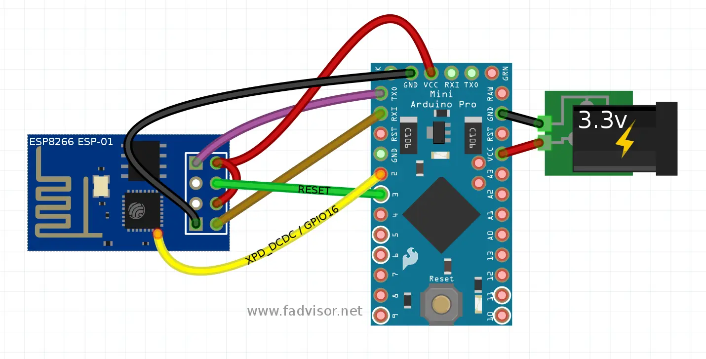
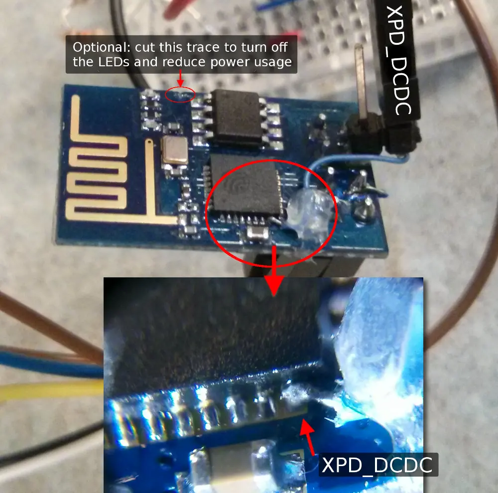
(Note, the ESP8266 ESP-01 has no exposed connection for the wake-up pin XPD_DCDC, put I soldered a wire directly to that pin on the chip which I have learned from this Blog while on other variants of the ESP8266 wifi module like ESP-07 and ESP-12 that pin would be the GPIO16)
Here is a code to show how it is done:
void sleepnow() {
  // Sent sleep command for 1 hour
  sendCommand("AT+GSLP=3600000");

  set\_sleep\_mode (SLEEP\_MODE\_PWR_DOWN);
  sleep_enable();

  // Set INT0 to trigger on Low Level (default)
  EICRA &= ~(\_BV(ISC01) | \_BV(ISC00));
  // Enable INT0 (Pin 2 on Arduino)
  EIMSK |= _BV(INT0);

  sei();

  sleep_cpu ();

  // After wakeing up disable sleep then
  // reset ESP8266.
  sleep_disable();

  pinMode(ESP8266\_Reset\_pin, OUTPUT);
  digitalWrite(ESP8266\_Reset\_pin, LOW);
  delay(100);
  digitalWrite(ESP8266\_Reset\_pin, HIGH);
  delay(100);
  // Stop setting it high to save power since
  // the wifi chip has its own pull-up.
  pinMode(ESP8266\_Reset\_pin, INPUT);
}

